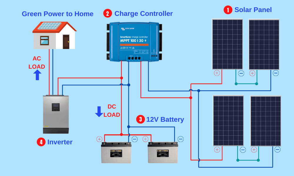
Were you aware that there is more than one way to connect the solar panels in your home solar system? In fact, there are two main techniques for wiring together solar panels, and each has different characteristics.
You can choose to wire up your home solar system in a series or a parallel arrangement. In this guide, I will give you a clear and understandable explanation of both types of electrical circuits and explain the benefits and disadvantages of each. So here’s everything you need to know about series versus parallel solar panels.
Some definitions
I’m going to be talking about electrical circuits, which are simply paths through which electrons flow. All the electrical items you use in your home are powered by electrical circuits. And your home solar setup is also powered by a flow of electrons through a circuit. Electrons, by the way, are the charge-bearing subatomic particles that give us electrical power.
What are Volts, Amps, Ohms, and Watts
We talk about electricity in terms of volts, amps, ohms, and watts. Here’s a quick recap of what each of these terms means. To make things easy to understand, we will use a water analogy. Since electricity flows in the same way as water, imagine an electrical circuit as a series of connected water pipes. Trust me; it’s simple.
Volts
Voltage is a measure of electrical potential energy. In our water pipe analogy, voltage represents the water’s pressure.
Amps
Amps measure electrical current. Using our water example, amps represent the rate of flow.
Ohms
The ohm is the unit we used to measure electrical resistance. In the water example, the width of the water pipe represents ohms or the resistance. It’s harder to push water through a narrow water pipe; this is the same as an electrical circuit with high resistance. If you make the water pipes wider, water can flow more easily. Similarly, if you lower the resistance of an electrical system, you increase its ability to transfer power
Here’s a quick formula explaining how these three units relate to each other.
Amps = Volts ÷ OhmsDon’t worry; this little formula is just explaining something quite obvious. Here’s what happens if we Express this using our water example.
Rate of water flow = water pressure ÷ pipe widthNow we can see how things change when we alter the system. If we increase water pressure but don’t change the pipe width, the water will flow more quickly.
Instead, if you widen the pipes, then water will flow more slowly.
And if you lower the water pressure, then the rate of flow will decrease.
It’s a simple way to see how the three main units of electrical measurement are interrelated
Watts
So, what are Watts?
Well, the Watt is the unit that we used to measure the power of an electrical system. Here’s how you calculate Watts.
Again think about the water comparison. If you use a hosepipe, the power of the jet is determined by both the water pressure and the speed at which the water is coming out of the hose.
Water power = water pressure x rate of flowNow that I have given you this quick recap let’s move on and look at the difference between series and parallel circuits.
What is a series electrical circuit?
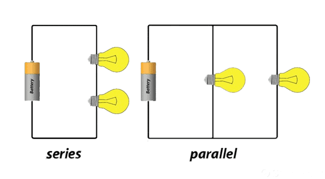
Looking at the above diagram, you’ll see that in a series of electrical circuits, a battery and two bulbs connect in a single electrical path.
What is a parallel electrical circuit?
In the example of a parallel electrical circuit above, the two bulbs are connected in separate sub-loops of the circuit. This changes things because the electrical current through a parallel circuit is split across the different components in the circuit.
How does a series solar panel connection work?
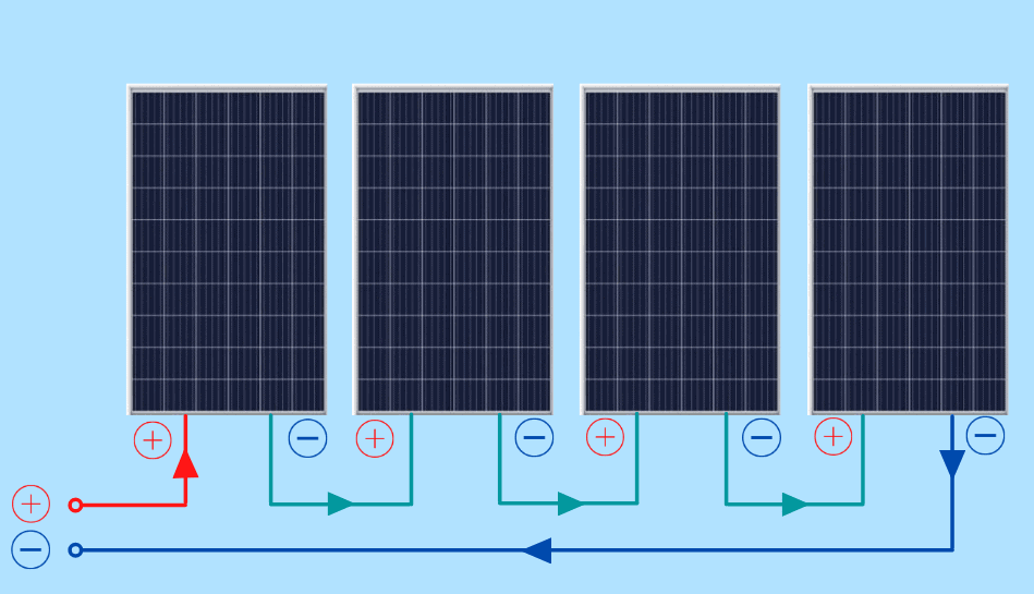
Let’s take a look at how we can connect some solar panels in a series circuit.
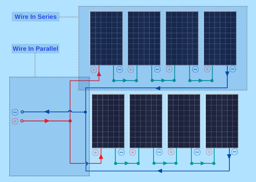
We’ll use an example of a series circuit connecting four 100 Watt solar panels. Each solar panel is 20 Volts and 5 Amps.
The circuit is formed by connecting the positive electrical terminal of one solar panel to the negative terminal of the next in a line and running a cable from each end of this line to the other components of our solar system. We can calculate the voltage current and power of this circuit as follows.
Total voltage = 20 Volts x 4 = 80 Volts
Total current = 5 Amps
Total power = 80 Volts x 5 Amps = 400 Watts
How does a parallel solar panel connection work?
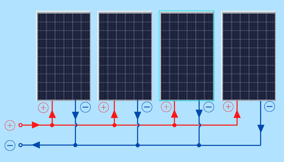
When we take these same four solar panels and connect them in a parallel circuit, we run the cables from each panel separately into our solar system. We don’t join any of the solar panels together. We’ll see why this is important in a little while. This is what the voltage, current, and power of our parallel solar panel connection look like.
Total voltage = 20 Volts
Total current = 5 Amps x 4 = 20 Amps
Total power = 20 Volts x 20 Amps = 400 Watts
Even though the voltage and amperage of our series and parallel solar connections are very different, you can see that the final power output is the same.
So we’ve proved that there is no difference in the power output from a series or a parallel solar system when the voltage and amperage of all solar panels are the same. But things get complicated when you wire together panels with different voltage and amperage capacities.
The effect of mixing solar panels in serial and parallel connections
Now let’s make the same circuits with three 100 Watt solar panels of 20 Volts and 5 Amps and another 75 Watt panel of 25 Volts and 3 Amps. This is the total power of 375 Watts.
The difference here is that when you wire different solar panels in series, you need to use the lowest amp rating of all the panels.
Serial Connection
Total voltage = 20 Volts x 3 + 25 Volts x 1 = 85 Volts
Total current = 3 Amps (taking the lowest rating)
Total power = 85 Volts x 3 Amps = 255 Watts
Because we had to use the lowest amperage panel for the series connection, we ended up with a total power output of 255 Watts, resulting in a loss of 375 – 255 = 120 Watts of power.
Now, when you wire the same panels in a parallel connection, you need to use the lowest voltage.
Parallel Connection
Total voltage = 20 Volts (taking the lowest rating)
Total current = 5 Amps x 3 + 3 Amps x 1 = 18 Amps
Total power = 20 Volts x 18 Amps = 360 Watts
When using the panel with the lowest voltage for the parallel connection, we ended up with a total power output of 360 Watts, resulting in a loss of 375 – 360 = 15 Watts.
If you’re not careful when wiring solar panels of different capacities, you can lose a lot of power. In these situations, it’s essential to look at the ratings and calculate the effects of serial or parallel wiring. But there are also some other advantages and disadvantages of these wiring systems that you need to take into account.
Advantages and disadvantages of series and parallel wiring systems
Wiring
If you are running an electrical circuit with high amperage, you need a thick cable to carry the load. Think back to the water example, where you’d need a strong pipe to handle a powerful flow of water.
Wiring your solar panels in parallel means that you need cabling and components rated for high Amperage. If you use serial wiring for your solar system, there will be a higher voltage and low amperage, reducing the demands on your cables and components. If you’re uncertain about which wire size to choose for your solar setup, you might find our article on how to choose solar wire size.
The main benefit of parallel wiring
When you wire all your solar panels in parallel, the performance of one panel is not dependent on the performance of the other panels. But in a serial connection, if one solar panel is working at a lower capacity, it reduces the whole solar array’s performance.
This is important in case a panel in a series connection malfunctions. Also, if a particular panel in the series may be receiving less sunlight because of shade, the whole system’s power output will be reduced.
Summary
Now you have a good idea about the differences between serial and parallel wiring systems. Each has its benefits and drawbacks, and you’ll need to think carefully about which one to use.
If you plan to connect solar panels of different capacities, then a parallel connection is probably best. Parallel connections will help you avoid an underperforming solar panel lowering the output of your whole system.
But remember, depending on your specific system requirements and the specifications of your panels, it may be more complicated and potentially more expensive to wire and connect your solar panel system in parallel.
Perhaps one solution is to carefully check the placement and performance of your solar panels so that if you choose to wire them in series, you can minimize the risks of performance loss.
If you have any comments or questions on this article about series versus parallel solar panels, then please share them here.

